Dolly Shot

Home

My latest LEGO stop-motion animation called for a scene where an actor walks down one side of a long street. After some experimentation, I found the best way to film this would be from the point of view of person walking at the same speed from across the street. In the film world this is knows as a dolly shot. The dolly refers to a cart or dolly that normally runs on rails. The camera and operator are placed on the dolly and is pushed by an assistant during the shot.

Doing a dolly shot in LEGO stop-motion animation is full of problems. The biggest is trying to move the camera at a steady pace in very small increments. For a minifig using a typical 8 step walk cycle, the camera must be moved just 2 millimeters each frame. Trying to keep the camera oriented at the same angle yet advance its position just 2 millimeters is a tough job. Placing the camera mount against a ruler is a possible solution, but only for short shots. I was planning one that was 700 frames long. That would be 700 chances to hit the camera and ruin the setup.

So I took the opportunity to build a dolly system for stop-motion animation. Some practitioners of this art form would insist that the solution itself must be made of LEGO. I am not such a purist and was willing to use a non LEGO system. A search of the web and a discussion on http://www.brickfilms.com provided no ready made solution in my budget. So I was forced to design and build a device to meet my needs.

The pictures show my basic solution. A wooden box supports two aluminum tubes used as the tracks for the dolly. A threaded rod is placed between the tubes. A captive nut on the threaded rod engages the dolly. A crank on the threaded rod is used to drive the system. With a fine pitched threaded rod, a full turn on the crank moves the car a barely noticeable distance.

Before I start with some building guidelines, let me go over some concepts and math. The distance between the centers of adjacent LEGO studs is 8 millimeters. Using a standard technique, a minifig moves forward two studs in 8 distinct positions. To track this action the camera must move at the same rate. If the animation is shot one frame per position, that means the camera moves 2 studs every 8 frames. Since a stud is 8 mm that means 8*2mm per 8 frames, or 2 mm per frame.

The ideal system would have the dolly travel 2 mm per crank rotation. To do this, the threaded rod must have a metric thread. In the US, such a threaded rod is not simple to find or buy. They are available in small quantities but at significant cost. For those living abroad, a metric threaded rod should be a close as your local hardware store. For those of us stuck in the dark ages, take solace. It is possible to use an imperial thread pitch and get decent tracking. Choosing a 1/4"x20 thread (20 threads per inch) means that each rotation advances the car by 1/20 inches or 1.27 mm. This translates to rotating the crank 1.57 times to advance 2 mm.

Obviously, keeping track and measuring fractional turns would be nasty. As it turns out, you can turn the crank 1.5 times and on occasion turn it twice to make up the lost fractional turns. If you are using a program like StopMotionPro that has markers, it is simple to monitor the drift and correct for it. If not, use a StickyNote on the screen to do the same job.
The following is not meant as detail construction notes, but rather hints to avoid the pitfalls.
  1. The length of the sides should be less than the length of the threaded rod. This is to leave enough rod outside the box to connect a crank to.
  2. The end blocks and the blocks that make up the dolly should be drilled at the same time. Temporarily glue them together during this phase. Use a drill press to insure the holes are all perpendicular. If you do not, the dolly will bind on the rods.
  3. Do not drill the hole for the camera mount above the threaded or plain rods. You will not be able to insert the bolt. Drill them between the rods.
  4. I made the captive nut by soldering a brass tab to a standard 1/4"*20 nut. The brass can be found at a hobby store. Pre drill the brass for the rod, and use silver solder.
  5. The captive nut could be permanently attached to the dolly with a simple screw. I choose a release mechanism to allow the dolly to be disconnected quickly. This is helpful when setting up the shot as it takes 20*36 turns of the crank to move from one end to the other.
  6. I made the crank from the same brass as the captive nut. It was soldered to a nut and the threaded rod at the same time. The handle was a long 4-40 bolt and a bit of brass tubing. If you leave a tiny bit of the threaded rod visible, you can use a cordless drill to drive the dolly long distances between shots.
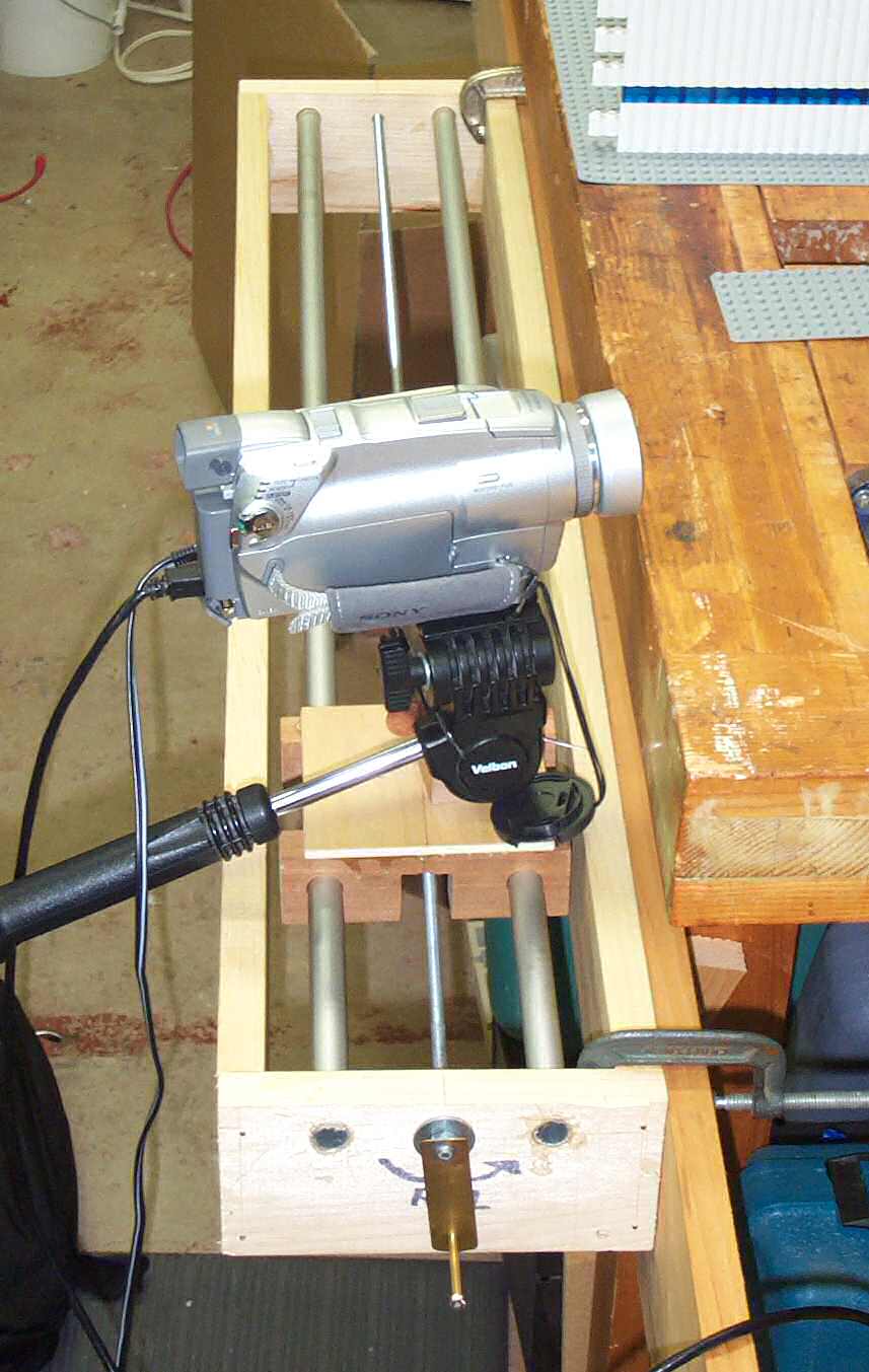
Overall view of the dolly.
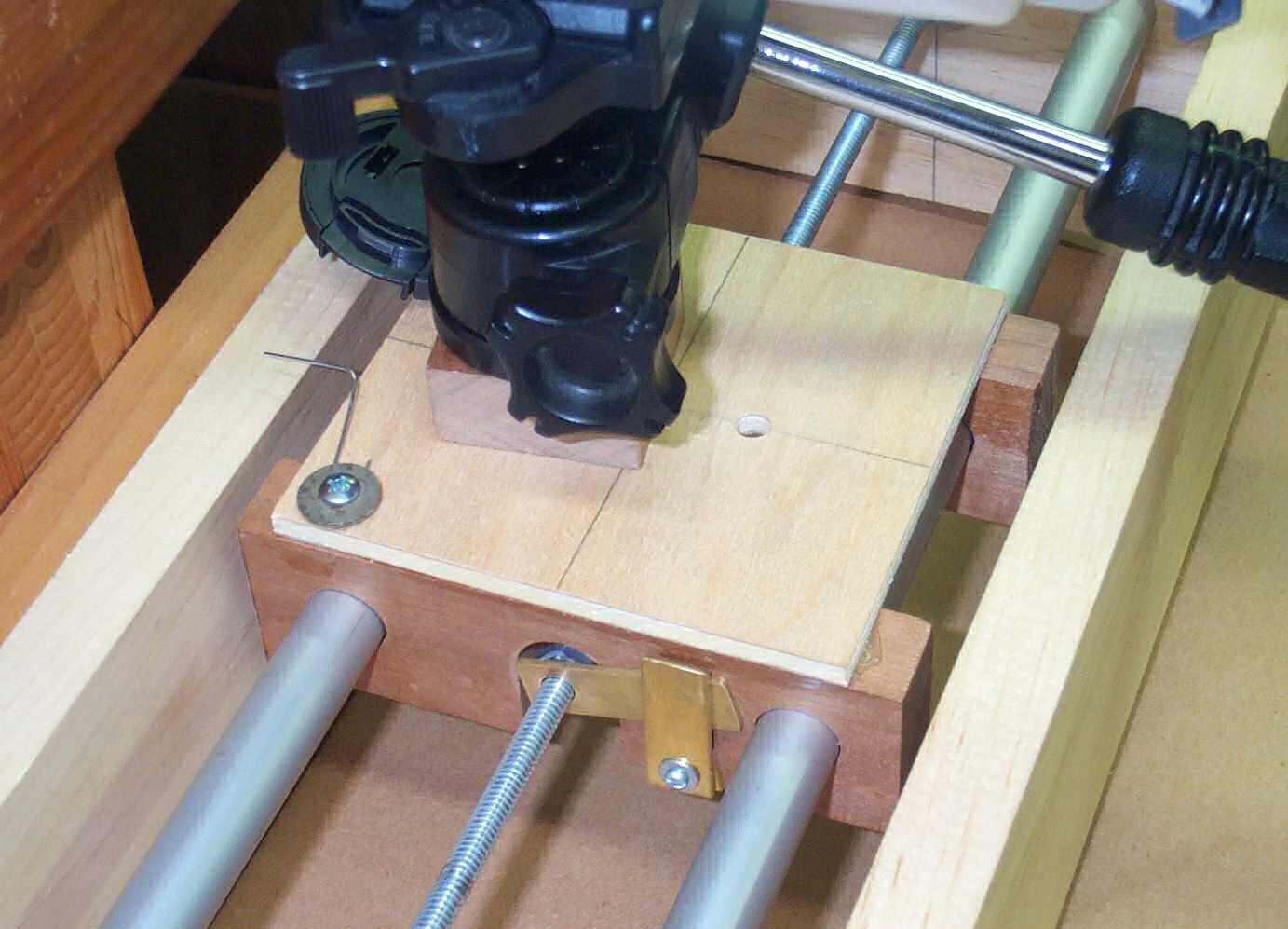
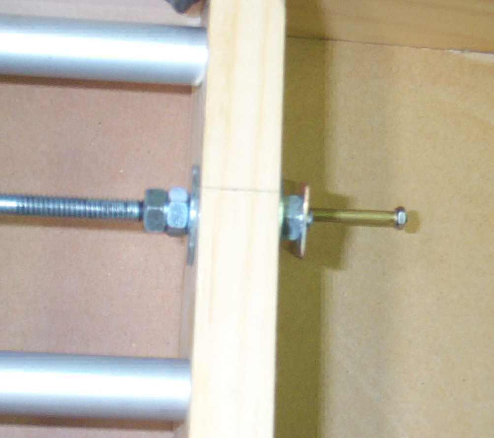
Closeup of the car on the rods and the threaded rod. Tripod head can be mounted to the car in a few positions.
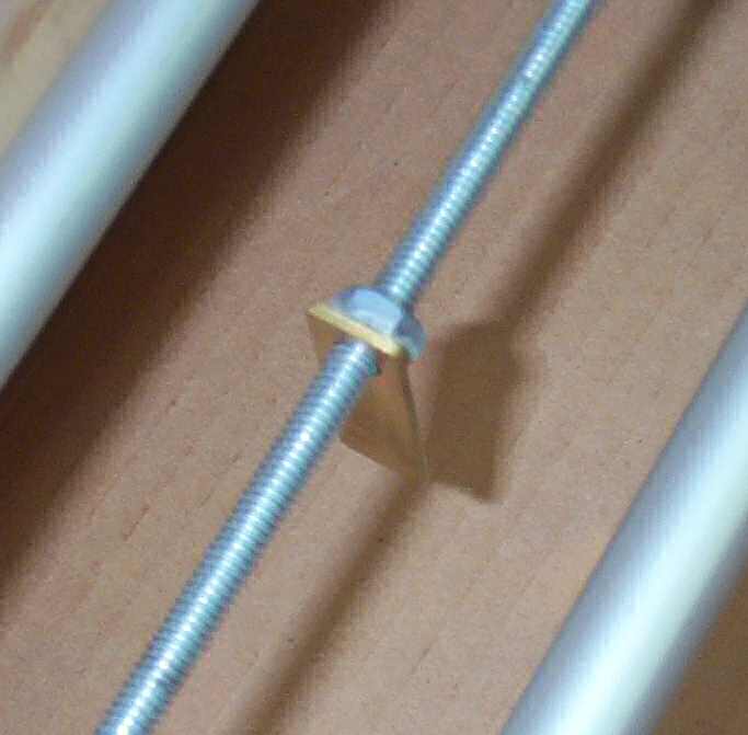
Closeup of the nut soldered to the brass tab.p
Closeup of the quick release mechanism. To not skimp on this step. Without a quick release, it takes forever to move the camera back and forth to setup and plan the shot.
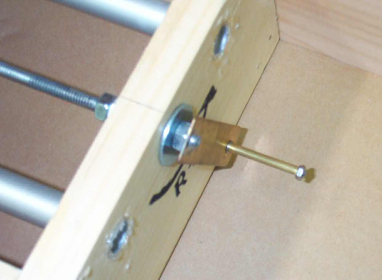
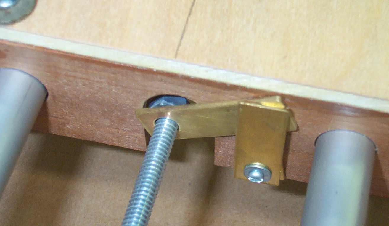
Details of the crank. I soldered the brass stock to a nut and the threaded rod. On the inside I used two nuts tightened against each other as a stop. Used some nice fender washers to reduce friction and wear.
More details on the handle.


Home

Copyright 2003-2017 Skye Sweeney; Last Updated on 2/21/2017